| Function module | Operation | Keyboard and mouse can finish all operations |
| X-ray tube control | Using mouse to click the X button can turn on or off the X-ray. The real-time tube voltage and current value will display beside, users can click up and down button, or drag the slider, or type to adjust. |
| Status bar | Indicates the interlock status, pre-heat status, and X-ray status by flashing alternately red and green. |
| Image effect adjustment | The brightness, contrast and gain of the image can be adjusted freely to achieve a satisfactory result. |
| Product list | Users can save the inspection parameters such as Z-axis position, brightness, contrast and gain, and can directly call the parameters when inspecting the same product, to improve the inspection efficiency. |
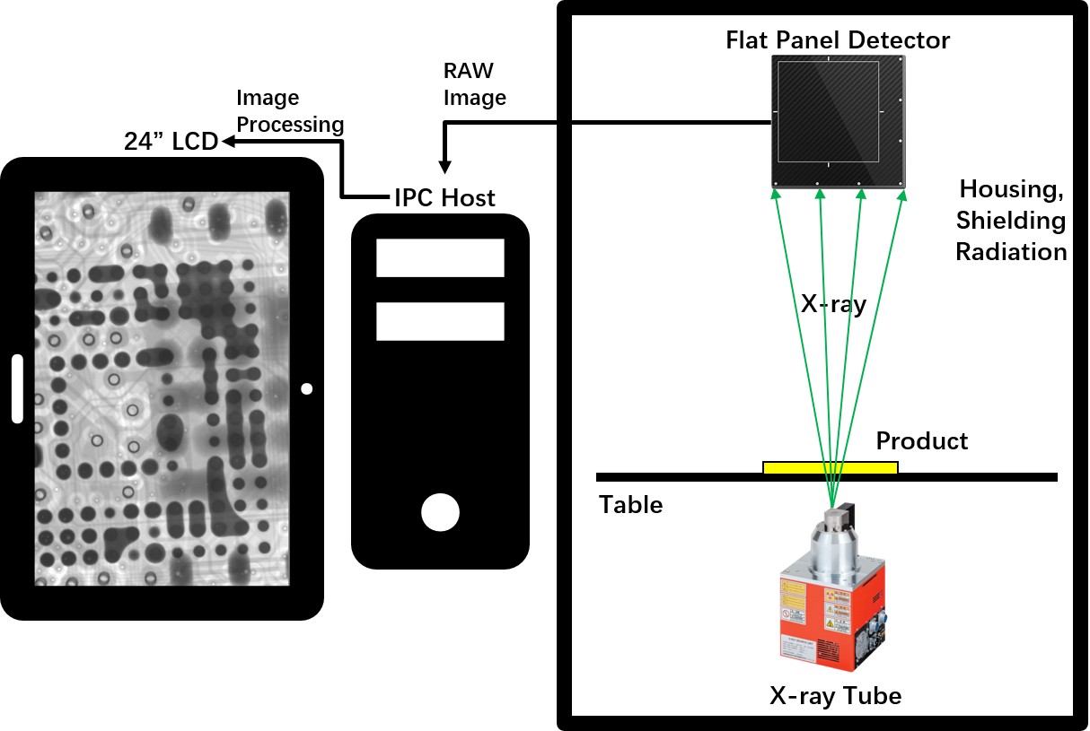
| Navigation window | After the camera takes a photo of the table, click anywhere in the photo, the table will move to the place you click and display on the screen. |
| Motion axis status | Display real-time coordinates. |
| Inspection result | The measurement results (voids rate, distance, area, etc., set by users) display in order. |
| Speed control | The movement speed of each axis can be adjusted to slow, normal and fast. |
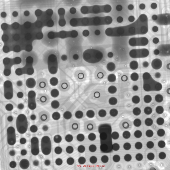
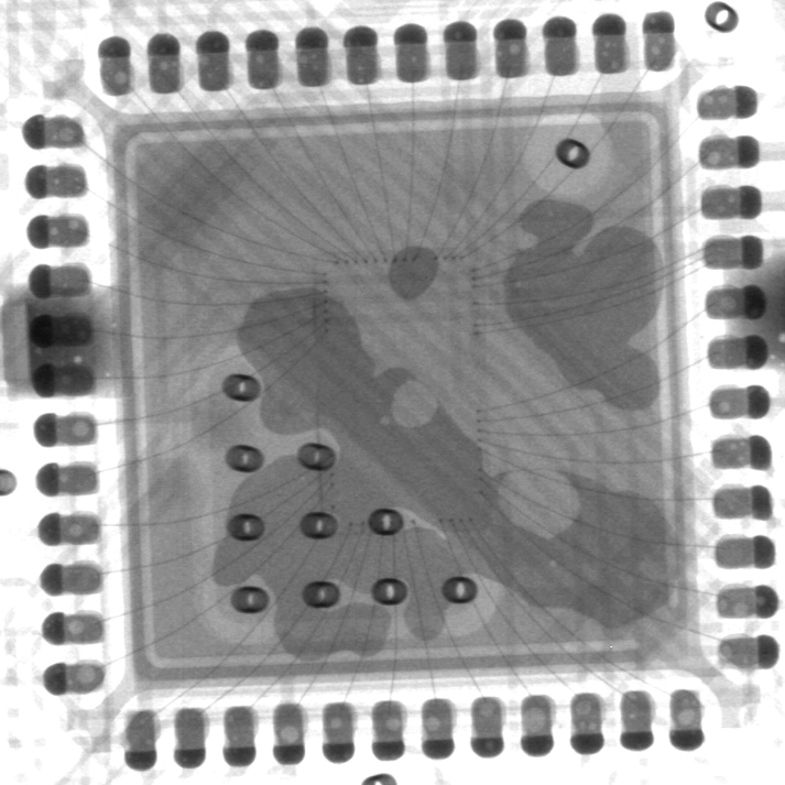
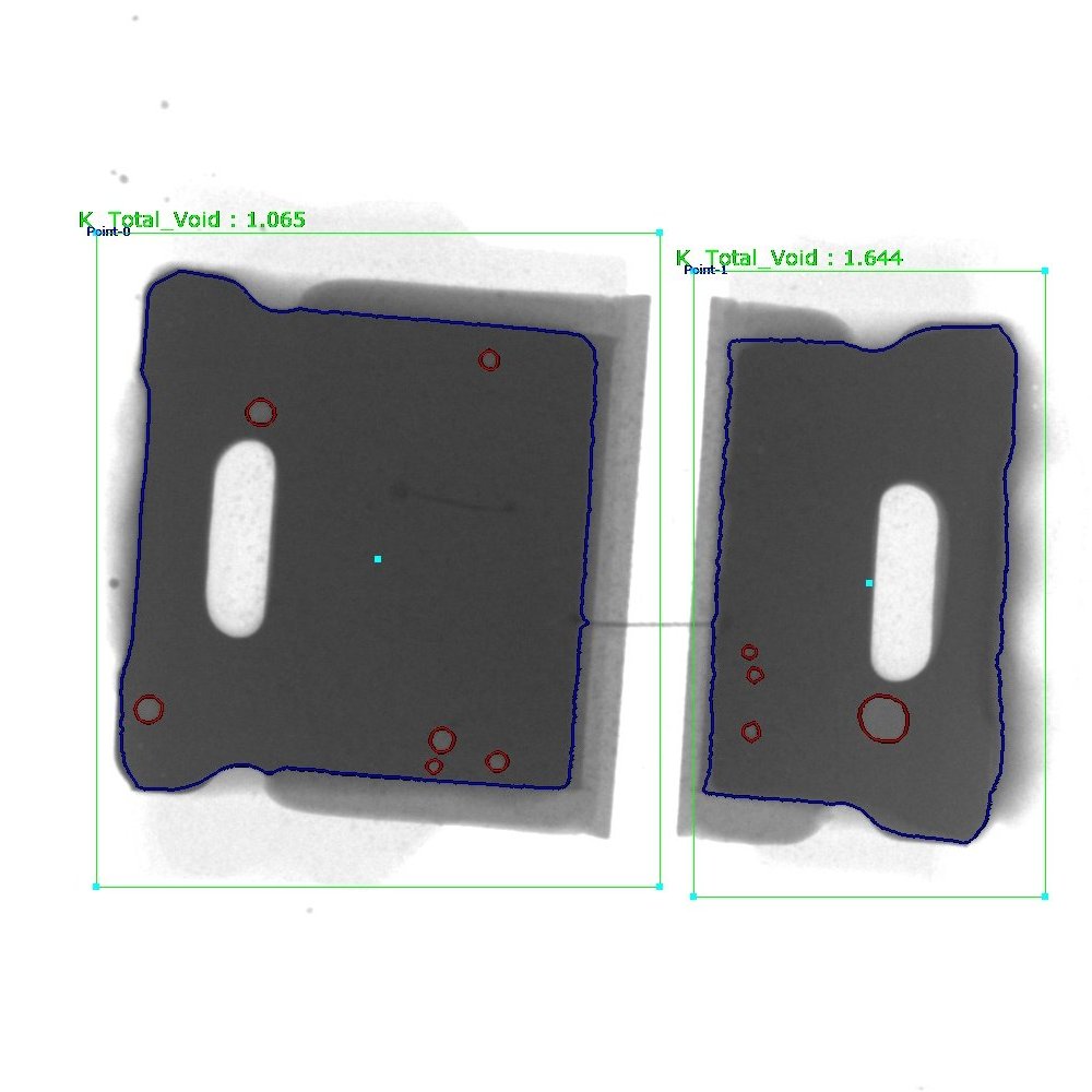
| Voids rate measurement | Automatic calculation | Click on two points to determine a rectangle. The software automatically finds and measures the edge of the solder ball in the rectangle, the pad and the internal voids, and can get the data of the voids rate, the area of the solder ball, the circumference, the biggest void’s rate, the length and the width, and indicates NG or OK by red and green. |
| Parameters adjustment | Users can adjust the grayscale threshold, pixel, contrast, size filtering and other parameters to get accurate results of automatic calculation. |
| Add voids manually | Users can draw a polygon or a free figure and calculate it as a void into the void rate. |
| Save parameters | Users can save parameters such as grayscale threshold, pixel, contrast, size filtering and other parameters, and can directly call the parameters when detecting the same product, to improve the detection efficiency. |
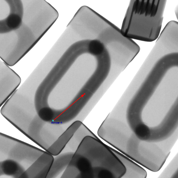
| Other measurement function | Distance | Click the A and B points to set as the baseline, then click the C point to measure the vertical distance from the C point to the baseline. |
| Distance rate | It is mostly used to measure the soldering rate of the through-hole. Set one more point “D” than the distance. Divide the vertical distance from the D point to baseline by the vertical distance of the C point, to obtain the percentage ratio of the vertical distance of D to C. |
| Angle | Click the A and B points to set as the baseline, then click the C point to measure the angle between the BA and BC rays. |
| Radius | It is mostly used to measure round components such as solder balls. Click three points to determine a circle and measure the circumference, area and radius. |
| Perimeter | It is mostly used to measure square components, click two points to determine a square, measure the length, width and area. |
| Automatic inspection | Manual setting | Users can set any positions on the table as inspection points, the software will automatically inspect and save the picture. |
| Array | For the regular inspection points, users only need to set two of the inspection points and the number of rows and columns, the software will automatically inspect each point and save pictures. |
| Automatic identification | For inspection points with obvious features, the software automatically identifies the positions, takes measurements, and saves the image. |
